As we have noted , the purpose of the rectifier section is to convert the incoming ac from a transformer or other ac power source to some form of pulsating dc. That is, it takes current that flows alternately in both directions as shown in the first figure to the right, and modifies it so that the output current flows only in one direction, as shown in the second and third figures below.
The circuit required to do this may be nothing more than a single diode, or it may be considerably more complex. However, all rectifier circuits may be classified into one of two categories, as follows:
Half-Wave Rectifiers. An easy way to convert ac to pulsating dc is to simply allow half of the ac cycle to pass, while blocking current to prevent it from flowing during the other half cycle. The figure to the right shows the resulting output. Such circuits are known as half-wave rectifiers because they only work on half of the incoming ac wave.
Full-Wave Rectifiers. The more common approach is to manipulate the incoming ac wave so that both halves are used to cause output current to flow in the same direction. The resulting waveform is shown to the right. Because these circuits operate on the entire incoming ac wave, they are known as full-wave rectifiers.
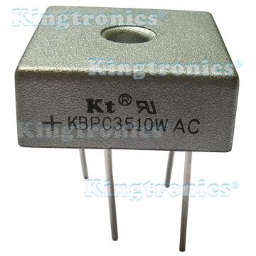
Kingtronics produce trimming potentiometers, dipped tantalum capacitors, multilayer ceramic capacitors, and diode & bridge rectifier. We are ready to respond each of your enquiry fastly and professionally .